- Position the handle forward to the front Forward Riser pulley
- Remove the handle rest bolts from the footboard and then angle the footboard away from the tank
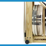
- Remove the aluminum tank cover by sliding it towards the footboard at an upward angle. See Video instructions.
- Carefully remove the Top Deck by removing the Top Deck bolts and upper Tie Rods. Gently lift the Top Deck up being careful not to dislodge any of the guide pulleys. Unclip the sensor connector from the wire assembly.
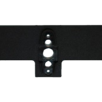
- Using the 5mm Allen key, remove the left key bracket. The left side being as you are sitting on the seat of the WaterRower. Also, the left key bracket is the bracket that does not house the S4 monitor. Set the key bracket and bolts aside.
- Using a small Phillips screwdriver, remove all of the screws on the S4 Monitor backplate housing then remove the 4 batteries in the S4 monitor.
- Un-plug the S4 Monitor wire assembly from the back of the monitor board, pull the faulty wire assembly through the spigot tube and discard the faulty wire assembly .
- Feed the replacement wire assembly through the spigot tube and clip into the S4 Monitor board. The smaller white connector end of the wire assembly fits into the S4 Monitor board.
- Reposition the S4 Monitor board to the backplate by screwing in the 4 small screws.
- Replace the batteries and battery cover
- Replace the left key bracket.
- Replace the top deck, ensuring that all the guide pullies and clutch shaft align with the holes in the top deck. Reinstall the Tie Rod assemblies and top deck bolts.
- Replace the M1 Tank Cover
- Move the footboard back towards the tank and reattach handle rests.
- Reposition the handle into the handle rests and the WaterRower is ready for use.
Related Articles
Series 4: Monitor Sensor Disk Alignment
If your S4 monitor is flashing zeros and not counting down, there is one simple check you can do that may solve the problem. You can check the position of...
Series 4: Cover Plate Replacement (push-button)
Step 1– Press the Heel Rest adjustment button and remove the Heel Rests as shown. Step 2– Using the 5mm Allen Key provided with the machine, remove the Heel Rest...
A1/GX: Sensor Modification
If the machine is not registering stroke rate, but distance and time are registering, there may be an issue with the sensor placement and it may need to be slightly...
M1: Top Deck Replacement
For Video Instructions, click here: Removing the Top Deck Step 1- Remove the handle from the handle rests and place the handle in the full forward position as shown....