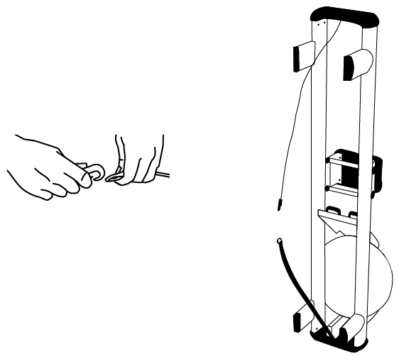
Step 1. Remove the handle from the handle rests and place the handle in the fully forward position.
Step 2. Stand the rower upright. Disconnect the bungee from the recoil belt, then lower the rower to normal position.
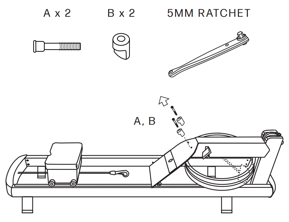
Step 3. Using the 5mm ratchet provided with your rower (or a 5mm Allen key), remove the handle rest bolts (A) and handle rests (B). Set them aside.
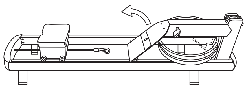
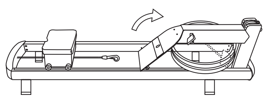
Step 4. Gently rotate the footboard rearward until it rests vertically.
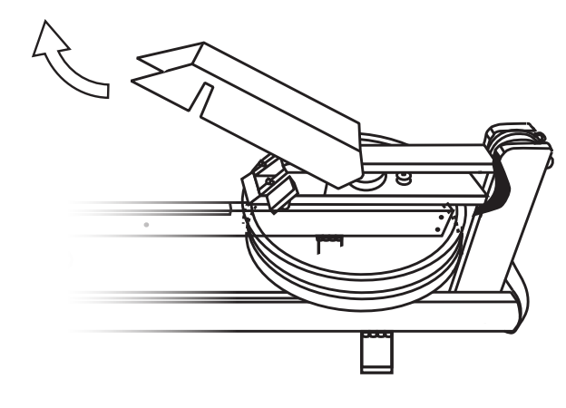
Step 5. Slide the top cover simultaneously upward and horizontally rearward (towards the rear of the rower) to reveal the clutch and recoil mechanism area. Be careful not to damage the monitor when removing the cover. Set the cover aside once removed.
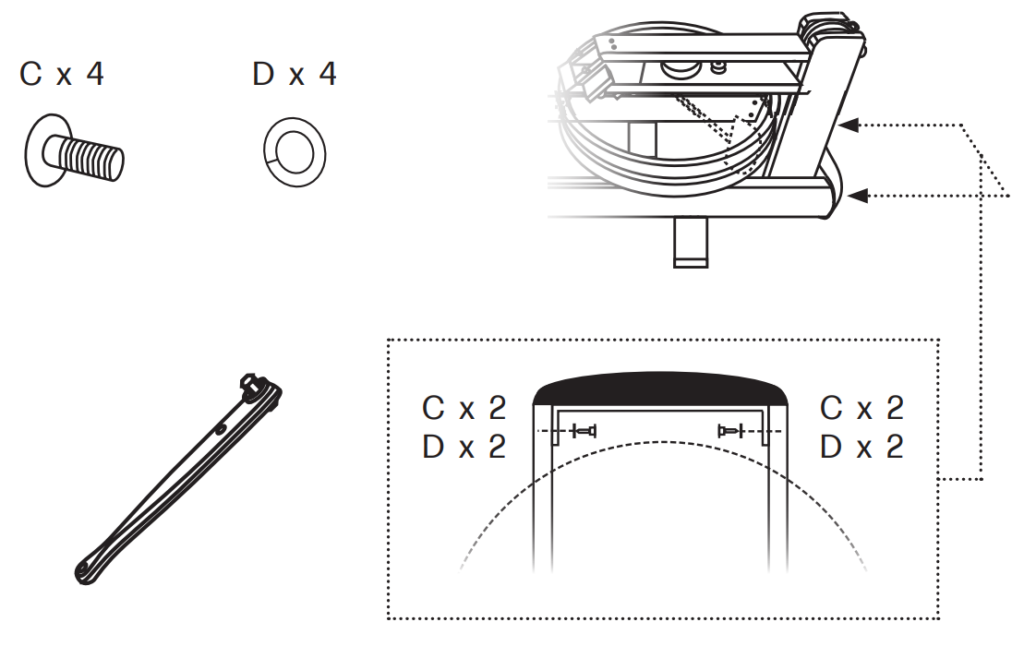
Step 6. Using the 5mm ratchet (or 5mm Allen key), remove the bolts (C) and washers (D) that secure the front end pad of the existing tank assembly to the rails. Set the hardware aside.
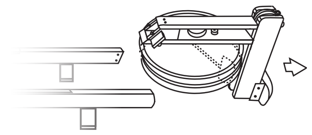
Step 7. Carefully slide the original tank assembly off the rails and set aside.
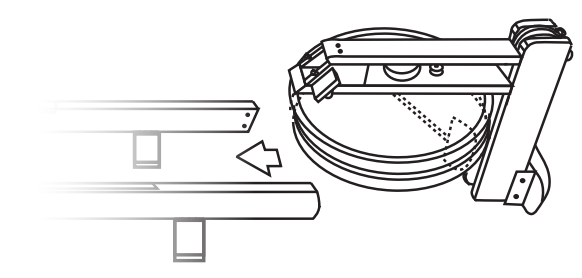
Step 8. Remove the replacement tank assembly from its box. Carefully place the tank assembly between the rails.
Note: The metal brackets protruding from the front end pad (on the tank assembly) fit inside the tubular section of the rails.
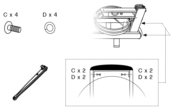
Step 9. Using the 5mm ratchet (or 5mm Allen key), secure the front end pad of the new tank assembly to the rails using the bolts (C) and washers (D) removed earlier.
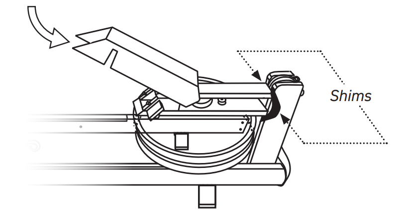
Step 10. Re-install the top cover. Starting just behind the monitor, position the cover at an angle. Slide the cover simultaneously downward and horizontally forward (towards the front of the rower) so that it covers the clutch and recoil mechanism area. Gently fit the front edge of the cover into the supporting / protective shims, if equipped.
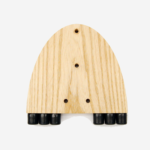
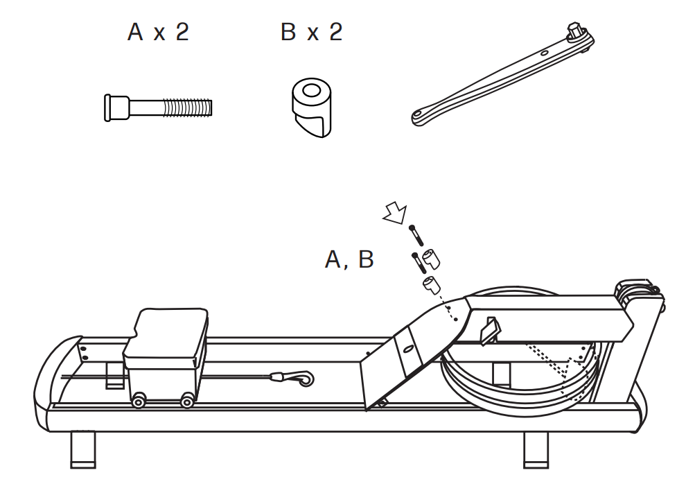
Step 11. Gently rotate the footboard forward until it rests against the slanted brackets of the tank assembly. The holes in the top of the footboard (for the handle rests) should align with the threaded inserts of the slanted brackets.
Step 12. Using the 5mm ratchet (or 5mm Allen key) and 2 handle rest bolts (A), install both handle rests (B). Ensure that the flat surfaces of the handle rests are parallel to the ground.
Note: This step also secures the footboard to the black slanted brackets of the tank assembly. Do not overtighten the handle rest bolts – permanent damage to the brackets may result.
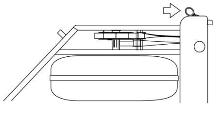
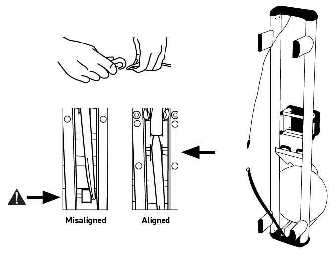
Step 13. Stand the rower upright, ensuring the bungee and recoil belt are accessible. Unravel the recoil belt from the bottom bracket of the new tank assembly. Feed the recoil belt over both guide pulleys in the forward riser and verify it is not misaligned. Connect the bungee to the recoil belt by linking the bungee’s hook with the recoil belt’s D-ring.
Step 14. Lower the rower to normal position and perform a few test strokes to confirm proper function of your rower. Happy Rowing!